
Connecting a Marshall reissue effects loop
Whether you’ve installed a Metroamp PTP board in your amp instead of the printed circuit board, or you’ve bought one of the Marshall effects loop boards separately from your local Marshall distributor to retrofit into your amp, this is a quick and easy guide on how to fit your effects loop.
Let’s start by naming the wires. Each wire should have it’s code silk-screened next to it’s turret, from W1 to W4.
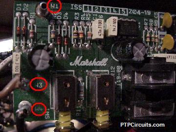
W1: Red wire, connects to 10w 47k resistor.
W2: Green wire, connects to ground.
W3: Brown wire, connects to circuit board where treble pot middle lug wire went.
W4: Black wire, connects to treble pot’s middle lug.
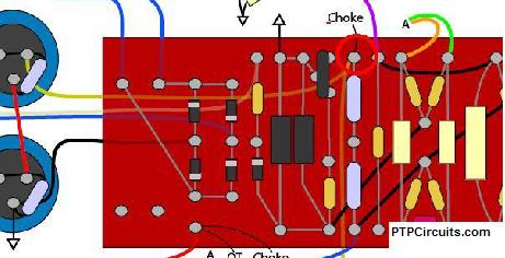
Basically the effects loop is inserted in-between the treble pot’s middle lug and the capacitor on the board which the middle lug was connected to (therefore it replaces the wire from the treble pot’s middle lug to the circuit board).
It’s advisable to twist together the green and black wires, and connect the green wire to the back of the treble pot or if you have a ground buss system, a point on the ground buss that’s close to the treble pot. For an even tidier job, you can also use cable ties or rubber bands to keep the two wires together. Run the two wires under the circuit board along the bottom of the chassis.
The red wire (W1) connects to a 10w wirewound 47k resistor. The other side of the resistor then connects to the voltage supply for the phase inverter and preamp, on the higher voltage side of the 8.2k/10k voltage dropping resistors where they meet the choke and screen voltage supply. On the below diagram I’ve circled the point in red for where the resistor connects to the circuit on a 100w Marshall 1959.
On the Marshall 1959slp, 1987x etc there is a special location for this resistor on the main circuit board, as you do not want this resistor hanging around in the air; it will be carrying between 300v and 400v, depending on how high your plate voltage is. If you don’t have anywhere on the main circuit board to put the resistor, I’d advise on creating a new small circuit board to mount it and run a wire from the 8.2k resistor to the resistor.
Copyright © Richard Baines 2006
Related posts: